- Dewatering of the construction sites such as the under-construction buildings, tunnels, underpasses, Shafts, etc.
- Undertaking of dewatering works and execution of dewatering projects from A to Z.
- Providing of pumping solutions, Removing & pumping water. (Dealing with floods and heavy rains).
- Dewatering Equipments and accessories for Rent (we have good amount of in-house storage of Pumps and accessories for dewatering system, which can be provided on rental basis as per the requirement.
- Call: +974 30301261
- Email us: info@ddcqatar.com
Our Services
Committed To Best Quality
- Home /
- Our Services
DDC Services
Dewatering Systems
DDC provide all kinds of the dewatering systems. Selection of the dewatering system and method depend on each project requirements.
Purposes of the dewatering
- To provide suitable working surface of the bottom of the excavation.
- To stabilize the banks of the excavation thus avoiding the hazards of slides and sloughing.
- To prevent disturbance of the soil at the bottom of excavation caused by boils or piping. Such disturbances may reduce the bearing power of the soil.
- Lowering the water table can also be utilized to increase the effective weight of the soil and consolidate the soil layers.
- Reducing lateral loads on sheeting and bracing is another way of use.
Methods of Dewatering
The most important available methods of groundwater control can be categorized as the following:
- Deep (bored) wells system with submersible pumps.
- Sumps & sump pumping.
- Shallow (bored) wells with pumps.
Deep Wells system
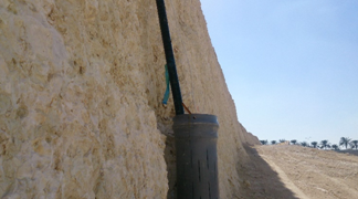
When water has to be extracted from depths greater than 8 m and it is not feasible to lower the type of pump and suction piping used in shallow wells to gain a few extra meters of depth the deep wells are such and submersible pumps installed within them. A cased borehole can be sunk using well drilling or bored piling rigs to a depth lower than the required dewatered level. The diameter will be 150 – 200 mm larger than the well inner casing, which in turn is sized to accept the submersible pump. The inner well casing has a perforated screen over the depth requiring dewatering and terminates below in 1 m of unperforated pipe which may serve as a sump for any material which passes the filter. After the slotted PVC or metal well screen (casing) has been installed it is surrounded by backfill over the unperforated pipe length and with graded filter material over the perforated length as the outer casing progressively withdrawn. The figure below is showing the components of the deep wells dewatering system.

Sumps and sump pumping
A sump is merely a hole in the ground from which water is being pumped for the purpose of removing water from the adjoining area. They are used with ditches leading to them in large excavations. Up to maximum of 8m below pump installation level; for greater depths a submersible pump is required. Shallow slopes may be required for unsupported excavations in silts and fine sands. Gravels and coarse sands are more suitable. Fines may be easily removed from ground and soils containing large percent of fines are not suitable. If there are existing foundations in the vicinity pumping may cause settlement of these foundations.
Subsidence of adjacent ground and sloughing of the lower part of a slope (sloped pits) may occur. The sump should be preferably lined with a filter material which has grain size gradations in compatible with the filter rules. For prolonged pumping the sump should be
prepared by first driving sheeting around the sump area for the full depth of the sump and installing a cage inside the sump made of wire mesh with internal strutting or a perforating pipe filling the filter material in the space outside the cage and at the bottom of the cage and withdrawing the sheeting. Two simple sumping details are shown in the below figures.

Wellpoint systems
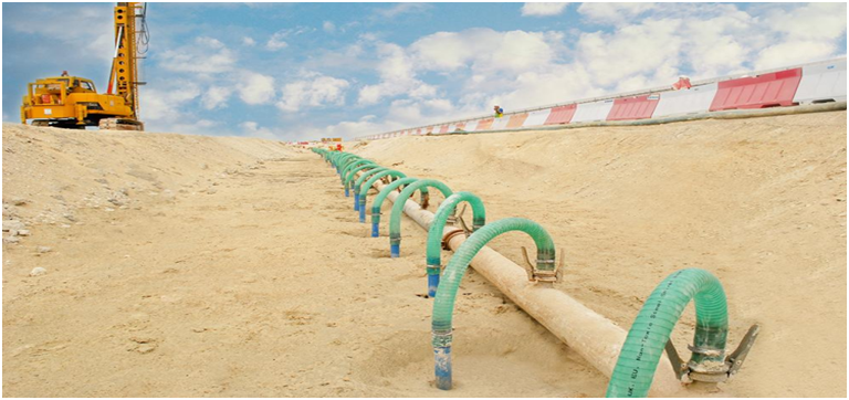
A Wellpoint are 5.0-7.5 cm diameter metal or plastic pipes 60 cm – 120 cm long which is perforated and covered with a screen. The lower end of the pipe has a driving head with water holes for jetting. Wellpoints are connected to 5.0-7.5 cm diameter pipes known as riser pipes and are inserted into the ground by driving or jetting. The upper ends of the riser pipes lead to a header pipe which, in turn, connected to a pump. The ground water is drawn by the pump into the wellpoints through the header pipe and discharged (Fig). The wellpoints are usually installed with 0.75m – 3m spacing. This type of dewatering system is effective in soils constituted primarily of sand fraction or other soil containing seams of such materials.The figure below is showing the components of the wellpoints dewatering system.
Shallow Wells
Shallow wells comprise surface pumps which draw water through suction pipes installed in bored wells drilled by the most appropriate well drilling and or bored piling equipment. The limiting depth to which this method is employed is about 8 m. Because wells are pre-bored, this method is used when hard or variable soil conditions preclude the use of a wellpoint system.
Selection of the method
The selection of one of these methods will depend on several parameters, while the combination of more than one method may be required as per the site conditions. The parameters should be taken in consideration during selection of the dewatering method to choose the most effective in both financial and technical and the effective dewatering method which minimize the environmental damage, protects the health and safety of on-site personnel and meets all legislative discharge limits.

